TRX250r.org

Author Topic: Proper Bridge Relief  (Read 2562 times)

Offline rsss396

Proper Bridge Relief
« on: July 31, 2013, 12:38:11 PM »
link to article: http://www.pilotodyssey.com/ExhaustBridgeRelief.htm


OK guys - you wanted to know this (hoser) so I've taken a few shots of a cylinder while I was working on it.
Let's look at the tools I use to chamfer the ports and relieve the exhaust bridge. From left to right - This is
a smooth spiral cut carbide cutter. Though it may show traces of aluminum on its teeth, it is what I use for
roughing in the chamfer on the ports of many large iron cylinders - like the one I'm about to show. It's a
68.5 mm bore TRX250R cylinder. Don't get me wrong. I do very little with this tool during this operation,
simply because it can remove too much material very quickly. When a cylinder is bored, even if it isn't
going to be ported, it's necessary to slightly 'dress' the edge of vertical port walls so the honing stones
don't catch them. The idea is to hone the cylinder without the stones snagging a port during every stroke.
Lightly dressing the edge of the vertical port walls, especially that of large ports, addresses this issue.
Next, to the cutter is a fine Cratex wheel. Obviously this isn't the order I use the tools in. I apparently
wasn't thinking that when I snapped the photo. It is used after the large Cratex wheel to its right.
The fine Cratex wheel is very fine. It takes quite a bit of time to remove the marks the rough
Cratex wheel leaves, but it takes much, much more time than that to simply relieve the bridge
with a fine Cratex wheel. The fine wheel doesn't really remove any material (to speak of) it just
removes the traces of the rougher tool. It leaves the surface shiny, with a smooth finish. A finish
that a piston ring could slide up and down on several million times without causing damage to it.
I also use the fine Cratex to finish the rest of the ports. It will polish out the marks made by even
the diamond wheel.
Now, the rough Cratex is just that - rough. I don't have a part number because I've had it for years.
I can tell you that it's 2" in diameter and the color of the wheel dictates how coarse it is. All of the
Cratex wheels are color coded. If you want one like this, ask for a tan 2 inch wheel with a 1/4"
drive. I'm sure it'll be the right one. It is necessary to turn this tool very slowly - v e r y s l o w l y ...
it removes iron in a hurry. On a thin bridge I spin the tool about 50 - 60 RPM and very carefully r
un it up and down the bridge, taking care to touch all of it equally if possible. When I'm about
half done, I turn the cylinder over and attack it from the other side. This tends to even out the
tools tendency toward wanting to remove more on the right side of the bridge due to its
rotation. It takes about 120 seconds total time.
Last is the diamond tool. I like the diamond impregnated tools for chamfering ports too.
Sometimes I do not use the spiral cutter at all for chamfering - I use the diamond instead.
is much more forgiving and is much harder to make a mistake with. This is especially
important with small bore cylinders. These tools come in all shapes so their use is widespread
throughout my cylinder work. I use them for iron port transfer walls where a carbide cutter wants
to bounce, or sometimes to reach in places where no other tool will go. They leave a fairly rough
finish on aluminum, but just about right for inlet and transfer ports. I use them even more in
NiCaSil cylinders. The diamond cuts the plating better than a carbide cutter does. A carbide
tool turning against a NiCaSil liner sounds like fingernails screeching down a chalkboard.
It rings so loud that ear plugs are a must. Any serious material must still be removed with
carbide, but be prepared to have a bunch of dull tools in a hurry when you use carbide
against NiCaSil - even for a moment.

Most of you guys know that when I'm porting a cylinder I like to have it bored first. This leaves room for
less error of the port timing and leaves less material to remove with hand tools. Boring a cylinder
'on size' or just slightly larger than the piston is perfect to me. In the first photo the bore finish is
rough - right off the boring bar. The red or pink you see is what's left after I used Berryman's B-12
and a shop rag to wipe most of the machinists die away. Just prior to this the scribe lines were visible.


I'm going to give this piston .0022" - .0026" clearance inside the bore. So, with that in mind and
knowing that I want to leave more clearance on the exhaust bridge than the piston gets in the
bore, I can rough the exhaust bridge in.
Rough size bore = 2.6975"
Piston = 2.697" (actual measurement)
Target bore size = 2.6992" to 2.6996"
Target (extra) exhaust bridge clearance = .0045" to .0065"
Final exhaust bridge measurement = 2.704" to 2.706"

I'll use the rough Cratex wheel and take the diameter of the bore at the exhaust bridge to about
2.7045", knowing the bore is already .0005 larger than the piston. Now I'll hone the cylinder to
final size
The final bore came out to 2.6996". The measurement at the bridge is (about) 2.7045" from
the rough wheel. With the fine Cratex I smooth out the cut marks and work the bridge from
the top and bottom to make it as uniform as possible. Since this cylinder has a bust port
(boost port) it is impossible to check the clearance at the exhaust bridge directly opposite
the boost port, so I'll concentrate on doing the best I can using the reflection of the light to
help point out imperfections - it's like looking down the body of a car. You can see flaws.
When I'm satisfied I've done my best I record the measurement. In this case it is 2.7052".
That puts me within the tolerance for the clearance I need.
Here's some things to go by when trying to decide how much bridge clearance to cut in:
The smaller the bore, the less extra bridge clearance is needed.
The larger the bore, the more extra bridge clearance is needed.
High compression builds need more clearance.
High performance builds always need more clearance than OEM non-ported.
High exhaust port requires more clearance.
Long power stroke requires more clearance.
Stroker motors require more clearance.

After writing this last bit out it seems that almost any build other than stock will require a
little more clearance than OEM. Honda claims .003" to .004" for their OEM TRX barrels -
actually that's a little more than I thought it said. I was thinking it said .002" to .003". I would
consider .003" to be absolute minimum for anything with even a high compression head
and/or a pipe and air cleaner. The engine will run with tighter clearance but you'll notice
local seizures in that area upon disassembly.
Anyone looking for a great builder I highly recommend the following.
For CP products dealers I would recommend:
Arlan at LED(site sponsor), Pete Schemberger at Hybrid Engineering, Mat Shearer at Shearer Custom Pipes, Dennis Packard at Packard Racing, and Nate McCoy of McCoys Peformance.

Other great builders I also would recommend: Neil Prichard, Jerry Hall, Bubba Ramsey and James Dodge.

Offline rsss396

Proper Bridge Relief
« Reply #1 on: July 31, 2013, 12:39:02 PM »
This photo shows the final hone, but the bridge is still rough from the big Cratex wheel.

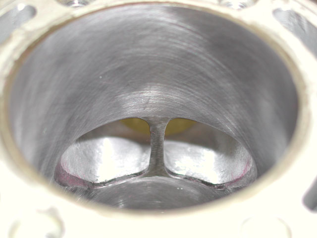
After some time (wearing a dust mask) using the fine Cratex the bridge is coming into it. Even
when done it will show some 'tracks' if you will, but it is smooth. Very smooth. Notice that I've
gone above the bridge (port window) and below it a little bit with the tool. This eases the
transition to the bridge - if the ring must use it.


With most of the bridge work done you can see its tracks. It's basically metal dust. There's
barely a texture at all in that area. It's much smoother than OEM. You may also notice the
exhaust port bevel at BDC. It is beveled where it needs to be. Further up the port in changes
into a rolled edge. In fact, I don't know if you can really see that in any of the other photo's. The
exhaust bridge also has rolled edges. The roundness to the corners of the exhaust bridge and
the exhaust port outer edges is worth plenty of power. Don't forget this important area.

Though I don't polish exhaust ports as a general rule, I do polish areas that always add power -
the corners, roof and bridge walls for about 3/8" into the port. This helps the exhaust gasses
leave the cylinder and is a bona fide speed secret.


Here are a couple of drawing of good and not so good chamfers. The first one is of transfer
ports - with mixture flowing out of them. The greatest amount of mixture will pass through a
transfer port, in less time, with less interference with the tunnel itself and the piston if its
contour is like the 'Best' picture.

The second drawing is of an exhaust port - with spent gasses flowing out of it. Notice the
difference between a standard 'quickie' chamfer and a chamfer nicely blended into its wall
and tunnel. There is a HUGE difference in flow between the two. Nicely chamfered ports
'act' like larger ports because of their free-flowing ability. These might seem like small things
(and they are - heh), but attention to detail here pays big dividends. Expect more horsepower
and torque due to port chamfers made like this.
Anyone looking for a great builder I highly recommend the following.
For CP products dealers I would recommend:
Arlan at LED(site sponsor), Pete Schemberger at Hybrid Engineering, Mat Shearer at Shearer Custom Pipes, Dennis Packard at Packard Racing, and Nate McCoy of McCoys Peformance.

Other great builders I also would recommend: Neil Prichard, Jerry Hall, Bubba Ramsey and James Dodge.


Sitemap 1 2 3 4 5 6 7 8 9 10 11 12 13 14 15 16 17 18 19 20 21 22 23 24 25 26 27 28 29 30 31 32 33 34 35 36 37 38