[TD=colspan: 3]
Component Definitions The entire crankshaft assembly must balanced (with the exception of certain rotating components marked* in the list below). For this illustration, we’ll assume that the engine in question is independently (internally) balanced; this means that all compensation for the weights mentioned above is made to the crankshaft itself, rather than to external components. The “classic” calculation requires dividing the engine’s crankshaft and related components into the two separate categories: “rotating weight” and “reciprocating weight”.
Rotating weight: » the crankshaft
» the oil mass of any hollow passages in the crankshaft
» the rod bearings (+ locating dowels, if any)
» the lower half of the connecting rod(s), including the caps & screws
» * any radially-symmetrical accessories attached to the crankshaft directly, but external to the
crankcase (cam drive sprocket, harmonic damper, pulley, flex plate, flywheel, fasteners, etc.),
that are inherently zero-balanced, and have no intentionally eccentric weight distribution
Reciprocating weight: » the pistons & piston components, including the pins, rings & locks (+ piston pin bushings, if any)
» the upper half of the connecting rods (except the piston pin bushings, if any)
However, a closer analysis of the components quickly shows that there are actually
three categories, not two: pure rotating weight, pure reciprocating weight, and “hybrid” weight.
Classifying the connecting rod’s upper and lower halves as “reciprocating” or “rotating” is not completely accurate. The rod’s pin eye does reciprocate, but the rod’s absolute upper end (including the material closing the top of the eye), and the rod beam between the pin eye and the crankshaft’s rod journal follow different and more complex paths. The rod’s big end does rotate, but only the imaginary line marking the contact with the crankshaft’s rod journal is “pure” rotation, the rod’s big end actually oscillates as well.
Let’s define
pure rotating motion as “motion which exactly follows the position of an imaginary point on the circumference of a circle, the diameter of which is the stroke length". These components
never come to a complete halt while the crankshaft is rotating and
never change direction. They vary speed directly proportionate to crankshaft RPM.
Let’s define
pure reciprocating motion as “bi-directional linear motion; accelerating from fully stopped @ TDC, traveling down, slowing & stopping @ BDC, then reversing and accelerating in the other direction, slowing & stopping, etc.”. These components come to a
complete halt twice in every crankshaft revolution. The speed of each cycle varies in direct proportion to crankshaft RPM. The speed at different points in each cycle varies with the ratio of the connecting rod length to the stroke length, and crankshaft position; their direction reverses twice (up to down) during each crankshaft revolution: at TDC (0°) and BDC (180°).
Let’s define
hybrid motion as “motion varying in speed with the component’s position along the rod’s length as well as engine RPM, but varying in direction based on crankshaft position: no lateral movement @ TDC or BDC. Its movement is in the same direction as the crankshaft, and has highest velocity when the rod’s beam axis is @ 90° to the crankshaft throw, which will occur between roughly 72° and 78° from TDC, depending on the rod ratio (not 90° from TDC).
Pure rotating weight » the crankshaft, etc. as described above
» the connecting rod bearings & dowels (if any)
Pure reciprocating weight » the piston(s) & piston components, including pins, rings & locks (+ piston pin bushings, if any)
Hybrid weight » the connecting rod beam
[/HR]
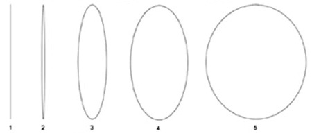
The Rod Path [h=3]Material closest to the center of the piston pin almost mimics the piston pin - its movement is reciprocating plus a small oscillation back & forth. Its path is a long, narrow irregular semi-ellipse with the minor diameter equal to the amplitude (span) of oscillation, and the major diameter equal to the stroke length (see #1 in the illustration below; the actual elliptical path would be irregular, and asymmetrical re motion away from TDC vs. BDC). Points farther down the rod’s beam and closer to the big end (see #2-4) have greater amplitudes of oscillations (minor diameter) added to the stroke length (major diameter), again forming an elliptical path, but of greater circumference and more regular shape.
The maximum oscillation is a function of the rod’s maximum angle of inclination to the bore axis, about 13 - 20° in most cases; this is determined by the rod to stroke ratio (longer rods = smaller angle). The outer limit of oscillation is therefore an isoceles triangle, with the apex at the piston pin centerline, and the 2 equal-length arms diverging off downward at twice the rod inclination angle (26 - 40°). The width of the triangle’s base is the maximum oscillation span or amplitude (the minor diameter of the ellipse), which is determined by the triangle’s height, a function of the placement along the rod’s beam axis of the point in question.
The beam closest to the piston pin (see #2) has an minor diameter amplitude
almost equal to zero, plus a major diameter equal to the stroke length - almost a straight line.
The beam closest to the rod journal (see #5) has an minor diameter amplitude
almost equal to the stroke length laterally, plus a major diameter equal to the stroke length - almost a perfect circle.
This means that the shape of the movement of each gram of weight, the speed of motion, and the distance traveled per revolution of the crankshaft all partially depend on its exact position along the rod’s beam axis, as well as the rod to stroke ratio, and the absolute length of the rod centers.
In the illustration (below, right), the motion of several points on the rod’s beam are depicted. Each point would travel the circumference of the shape shown during one rotation of the crankshaft, arriving back at the top @ TDC each time.[/h][/TD]
[/TR]
[TR]
[TD][h=3]
#1 shows the motion of a point on the rod’s beam axis centered in the pin eye - the motion is completely reciprocating. The major diameter for all ellipses shown is the stroke length (here shown at 4.00”), but since there is no oscillation there is therefore no rotation, and the minor diameter (the width) of the ellipse is 0 - the shape is a straight line.[/h][/TD]
[TD=width: 10] [/TD]
[TD=align: right]
[TD=align: right]
[/TD]
[/TR]
[/TABLE]
[/TD]
[/TR]
[TR]
[TD=colspan: 3][h=3]
#2 shows a point slightly
below point #1 along the rod’s beam axis. The minor diameter is about .10”, representing a small back & forth oscillation.
#3 shows a point below point #2 along the rod’s beam axis. The minor diameter is about 1.00", representing a larger back & forth oscillation.
#4 shows a point slightly below this point along the rod’s beam axis. The minor diameter is about 2.00”, representing a path with much more rotating motion.
#5 shows a point almost at the big end of the rod, just above the upper rod bearing. Here, the minor diameter is almost the stroke’s full length of 4”.
The next logical step down the rod’s beam axis would, of course, be pure rotating weight, forming an ellipse with the minor and major diameters at stroke length - a circle, the exact path of the crankshaft’s rod journal.[/h][/TD]
[/TR]
[/TABLE]


