Dave could you explain to me how to test, the coil output?
I have access to just about any type of meter available, and im wanting to learn how to do what your talking about..
obviously checking the coil resistance, and peak voltage... but it sounds like somehow your actually checking the spark intensity...or are you just checking peck voltage with the different cdi's?? thanks
Barry
2 years ago I went after trying to actually figure out spark intensity on different CDI's, well I am pretty much still trying.
What I have used for testing different parts of the circuit from the stator - CDI - coil - spark plug
I spin the flywheel/stator/coil/spark plug assembly with a bench tester that can run from 500 rpms to 10,000 rpms
What I have for testing equipment is:
- Equus 5568 Pro-Timing Light
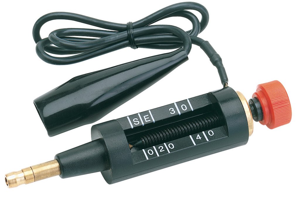
- TecMate's "Ignitionmate"
The compact dual-display peak-voltage ignition tester that makes trouble-shooting all types of spark ignition systems easier, surer, quicker. Ignition signals are fast, high voltage, pulses of energy that can damage even a good digital multimeter whereas the IgnitionMate has been specially designed to measure and dynamically display both primary and secondary ignition signals on bright LED bargraph displays.
The application of this versatile tool is based on two basic points:
- Different types of ignition systems have the same basic components with signals measured being generally similar in nature and magnitude.
No disassembling of ignition components are required. (This avoids accidentally introducing, or correcting, poor contacts in the system, which may further confuse and delay resolution of the unidentified problems.)
- The power-sports vehicle industry’s most recommended problem-solving ignition trouble-shooting tool includes the following measurement options:
Primary low tension / peak volt 10, 40 or 400Vpk scales - use the RED & BLACK silicon tester cables to measure primary signals between the ICU and the power supply (battery or charge coil), timing pick-up (pulse coil or hall sensor), ignition coil and switches (key, emergency stop, footstand, throttle). The silicon tester cables are resistant to damage from hot engines or exhausts. Also included are insulated crocodile clips and special PROBULATOR back probes that allow easy connection (without damage) to in line cable connectors.
[/LIST]
Secondary high tension / peak volt 10, 20, 40 kV scales - use the caliper to measure high voltage between the ignition coil and the sparkplug. Use the
+/- switch to determine the polarity of the high voltage signal. Normally single output coils have negative signals and dual output coils have negative and positive signals.
Spark scale to measure the consistency of the high voltage current signal and to determine misfires. The signal strength can be varied for display purposes. Spark strength of different cylinders can be compared.
The dual displays allow simultaneous measurement of two different ignition signals. This allows you to narrow down between which two points the problem lies.

- Smarttach
TA100 Features Tachometer function - For 1 to 12 cylinders and 2 or 4 cycle engines
- Measures from 200 to 20000 RPM on a 4-1/2 digits LCD display
- Advanced microcontroller technology yields 0.5 % accuracy
- No sighting of rotating parts or hook-up required.
- Works on DIS, Conventional, Magneto and most spark ignition system.
Secondary ignition tester - Instant digital readings from 0 to 40000 Volt
- Special antenna sensor allows quick hook-up to spark plug and ignition coil wires
- No ground wire connections required, for fast troubleshooting
- Multiple diagnostic applications are described in comprehensive User's Handbook (Included)
Simple and easy to use - Tachometer: Set the number of cylinders and cycles, extend the antenna and hold the instrument about a foot above the ignition system. RPM is displayed.
- Secondary Ignition Voltage Tester: Hook the antenna sensor over a spark plug wire or coil. Peak voltage of the ignition pulse in kilovolts is displayed
Technical Specifications - Display: Large 4-1/2 Digits LCD
- Tachometer Range: 200 to 19999 RPM
- # of Cylinders: 1,2,3,4,5,6,8,10 and 12
- Cycles: 2 and 4 Cycles
- Accuracy: ± 0.5%
- Response time: 0.5 Seconds
- Ignition peak voltage range: 0 to 39.9 KVolt
- Antenna: Collapsible 5 sections with capacitive sensor pick up
- Secondary ignition pick up: Capacitive sensor
- Spark Ignition System: Distributor, Magneto and D.I.S.
- Power Source: One standard 9 Volt alkaline battery type NEDA 1604 IEC 6F 22
- Battery life: Approx. 200 hours of operation
- Power Saving: Auto power off after approximately 3 min. of inactivity
- Physical dimensions: 2.75" W x 5.35" L x 1" D - ( 69.9 x 135.9 x 25.4 mm )
- Weight: Approximately 6.2 Oz ( 180 g) Including battery
Electrical Specifications - Maximum spark plug wire voltage (Through capacitive pickup only): 39.9 KVolt

I also use a Fluke 73 and a Fluke 123 to measure current and voltage on the output of the CDI
I also have also tried using a high voltage probe with my flukes to measure actual spark output but not with much luck

I am at work today and many of my old notes have been thrown away over the last few years but I will just say spark energy is not a easy thing to measure. I read up allot on the subject back then but there are many variables to account for.
The ignitionmate does a pretty good job with the output reading for spark energy but did see inconsistencies and the smart tach is a waste of money along with the high voltage probe.
After not being 100% satisfied with my spark out put I figured I would just measure amperage the coil was pulling on the primary side which is typically about 300v so the flukes can be directly connected in series with the coil and for the most part is pretty consistant but the capacitor's discharge does mess with the output reading.
So I then looked at the stator amperage along with the CDI amperage.
While for the most part everything was consistant with the meters but sometimes the outputs seamed as I will call strange, Like I said I am at work so I dont have what notes I have left but I do know while the MSD Enhancer CDI had the brightest and loadest spark it had strange low amperage readings so I feel that the meters were not always accurate.
I am not a electronics guy and I wish I knew someone close that could come by and work with me to truly analyze spark energy that these CDI put out.
I even played with one of these and boy the CDI's dont like the noise they make